
Custom Gear Tool Drawing Checklist: What to Confirm Before Production
A custom gear tool drawing is the point where a quotation becomes a manufacturing instruction. Before approval, the practical question is not whether the drawing looks complete; it is whether the gear geometry, machine interface and cutting conditions are stated clearly enough for engineering to confirm the intended tool.
This checklist is for manufacturing engineers and purchasing teams preparing a custom gear-hob inquiry. It helps turn an approval risk into a reviewable package without assuming a tool material, coating or process result that has not been confirmed for the application.
The short answer: confirm the gear, the mounting and the cutting condition
At minimum, a custom gear hob request needs the exact module or diametral pitch, pressure angle, workpiece tooth count, material and hardness, required accuracy class, and the intended bore or shank arrangement. The source guidance also identifies starts, hand of cut, outside diameter, bore/keyway, coating request and flute count as specification fields to review.
Treat these as inputs for engineering confirmation, not as a substitute for an application-specific tool design. If any value is unknown, mark it as open rather than copying an assumption from an earlier part or a similar machine.
Step 1: Verify the tooth-form information from the gear drawing
Start with the design values in the original unit system.
- Record the exact module or diametral pitch (DP). Do not round a converted value; provide the original design value for confirmation.
- Record the pressure angle. The source notes that 20° is common but not universal; 14.5° can occur in legacy applications, and 25° is also listed. The drawing or specification must decide the value.
- Record the number of teeth and helix angle. The helix angle determines whether a helical or straight-flute hob is required.
- Include the referenced DIN, ISO or AGMA requirement where it appears on the drawing.
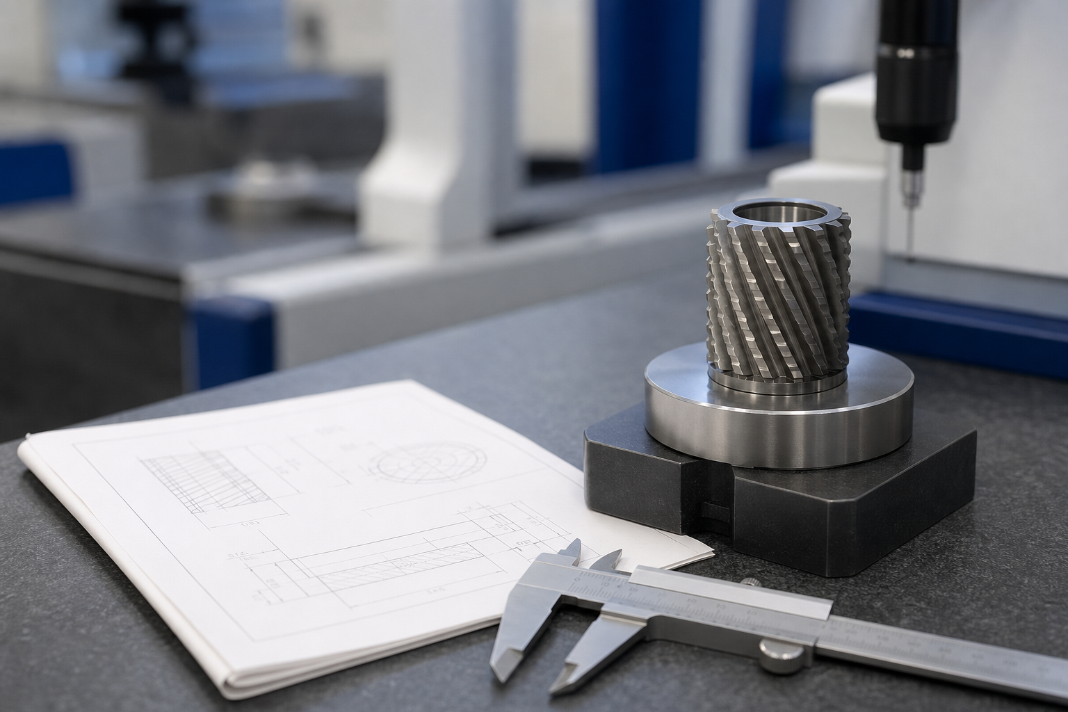
The gear drawing maps its module/DP, pressure angle, material and hardness, quality grade and helix angle into the main inputs for a hob quotation. Sending the original drawing alongside this checklist lets engineering verify that mapping before production.
Step 2: Check the machine interface before approving the tool outline
A correct tooth form is not enough if the tool cannot mount on the intended machine. Review the physical interface against the actual arbor and clearance constraints:
| Drawing field | What to confirm |
|---|---|
| Outside diameter | Unit and available arbor clearance |
| Bore diameter and bore length | Exact value and unit |
| Keyway | Whether needed, plus width and depth where applicable |
| Hand of cut | Right-hand or left-hand requirement |
| Number of starts | Single- or multi-start requirement, or an open item for engineering review |
| Number of flutes (gashes) | Specified value or a request for Nobeve’s recommendation |
The custom specification guide specifically warns that an omitted bore diameter can make a hob unusable without re-boring. Confirm bore, bore length and keyway requirements against the machine documentation before signing off.
Step 3: State the workpiece condition and process bottleneck
Do not name only the workpiece material. Provide the measured hardness value and scale, such as HRC or HB, and state the condition in which it was measured. The source explains that material and hardness are used to select the substrate and coating; the same alloy at different hardness levels can require different hob configurations.
Also document the actual machining context for the review:
- Machine model, spindle and arbor arrangement.
- Cooling method at the cut.
- Current or intended cutting speed and feed, if known.
- The production bottleneck to address, such as clearance, setup stability, tool life concern or required throughput.
- Any vibration, interrupted engagement or access constraint that engineering should evaluate.
These fields do not establish a performance claim. They give engineering the machine condition and bottleneck needed to assess the proposed geometry and tool family.
Step 4: Review accuracy and inspection requirements
Put the requested accuracy class on the drawing or attach the governing customer requirement. The guide lists DIN AA, DIN AAA and AGMA classes as possible accuracy inputs, and states that the requested class affects grinding time, inspection cost and price.
If the drawing specifies target gear quality rather than hob accuracy, include that requirement and ask engineering to confirm the required tool accuracy. Do not convert between standards or select a class solely because it appeared on a prior order.
Step 5: Separate tool sourcing questions from engineering confirmation
Keep the inquiry precise about what is being requested. For a custom gear hob, submit the drawing and cutting inputs above for a tooling review. If the requirement is HSS hob sourcing, identify that separately from a carbide tool package inquiry and state the desired tool substrate, material/source requirements and the application details that still need confirmation.
For either request, do not approve a coating, substrate or cutting condition from a generic rule. Nobeve’s documented workflow reviews the drawing, confirms the pitch system, pressure angle and accuracy class, then recommends substrate and coating from the workpiece material and hardness before production begins.
A final approval checklist
Before releasing the drawing for production, make sure the package includes:
- The original gear drawing or specification, with its original metric or imperial values.
- Module or DP, pressure angle, tooth count and helix angle.
- Workpiece material, measured hardness value and hardness scale.
- Required DIN, ISO or AGMA quality/accuracy requirement and inspection expectation.
- Outside diameter, bore diameter, bore length, keyway and arbor-clearance information.
- Hand of cut, starts and flute requirements, or clearly marked questions for engineering.
- Machine condition, cooling method, planned parameters and the production bottleneck.
- A written engineering confirmation of the interpretation before manufacturing starts.
Next step: send a reviewable drawing package
For a broader view of how drawing approval fits into a custom order, see the custom gear tools lead-time process. When the checklist is complete, send the drawing and the open questions through the Nobeve contact page for an application-specific review before production approval.