The Internal Spline Problem No One Talks About Openly
You’ve lined up the machine, checked the tolerances, and confirmed the material specs. Everything looks right on paper. But the moment your standard power skiving cutter hits that internal spline bore — especially one with tight clearance constraints or an unusual helix angle — the tool chatters, the profile drifts, or worse, the cutter chips on the first pass.
Sound familiar? If so, you’re not alone. Internal spline cutting is one of the most geometrically demanding operations in gear manufacturing, and off-the-shelf power skiving cutters simply aren’t designed for the wide range of part geometries encountered in real production environments.
This article explains exactly how Nobeve — a specialist gear tool manufacturer — approaches custom power skiving cutter design for internal splines. We cover the engineering constraints, the optimization workflow (from drawings to cutting profiles), and the material choices that determine whether your process succeeds or fails. Whether you’re a manufacturing engineer dealing with a specific machining bottleneck or a purchasing professional evaluating tooling partners, this guide will help you ask the right questions and make the right decision.
Why Internal Splines Challenge Standard Tooling
The Geometry Problem: Clearance Is Everything
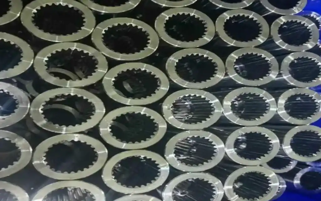
Unlike external gear hobbing, power skiving of internal splines requires the cutter to operate inside a bore. This creates a fundamental conflict: the cutter needs enough body mass to be rigid and resist cutting forces, but it also needs to clear the bore wall without interference.
The cross-axis angle (also called the interference angle) between the cutter spindle and the workpiece spindle is the critical variable. Too small an angle, and material removal efficiency drops. Too large an angle, and the cutter body physically interferes with the bore. Finding the exact sweet spot for a given part requires custom cutter geometry — not a catalog lookup.
According to the Gear Research Institute, power skiving productivity depends heavily on achieving the correct axis crossing angle, which must be matched to module, tooth count, and available bore clearance. Standard tools handle a narrow band of these parameters. Custom tools handle the rest.
The Material Problem: Soft vs. Hard Workpieces Behave Completely Differently
A second major challenge is workpiece material. Internal splines are machined in everything from low-carbon case-hardening steels (≤HRC30) to fully hardened alloy steels (up to HRC50+). The cutting forces, chip formation patterns, and tool wear mechanisms are dramatically different across this hardness range.
Choosing the wrong substrate — carbide where you need toughness, or PM-HSS where you need speed — is one of the most common and costly mistakes in spline tooling. We’ll address this directly in the material selection section below.
How Nobeve Designs Custom Power Skiving Cutters: Step by Step
Nobeve’s custom tooling workflow begins not with a catalog, but with your engineering drawings. Here’s how the process works from first contact to cutting.
Step 1 — Drawing Review and Reverse Engineering
Customers submit DXF, DWG, or STEP files describing the target spline: module, tooth count, pressure angle, helix angle, bore diameter, and any special fit classes (e.g., DIN 5480, ISO 4156). If a worn or broken legacy cutter exists, Nobeve’s engineering team can reverse-engineer from the physical tool using CMM measurement and 3D scanning.
The output of this stage is a verified tooth profile specification that accounts for protuberance (undercut) requirements, tip relief, and any necessary profile shift — details that directly affect the spline’s functional fit and load distribution.
Step 2 — Interference Angle Optimization
This is the core engineering step. Given the bore geometry and spline parameters, Nobeve’s engineers calculate the range of feasible axis crossing angles using a combination of analytical formulas and 3D simulation of cutter-workpiece engagement.
The optimization targets two competing objectives simultaneously:
- Maximum material removal efficiency — favors larger crossing angles
- Zero body interference — restricts crossing angle based on bore ID, shoulder clearances, and cutter OD
- Surface finish stability — crossing angle affects the effective rake angle at the cutting edge, impacting finish
- Tool life — smaller angles reduce cutting velocity component, which directly affects wear rate
The result is an optimized crossing angle specific to your part, not a compromise based on what the catalog happens to offer.
Step 3 — Cutting Profile Calculation and Relief Angle Design
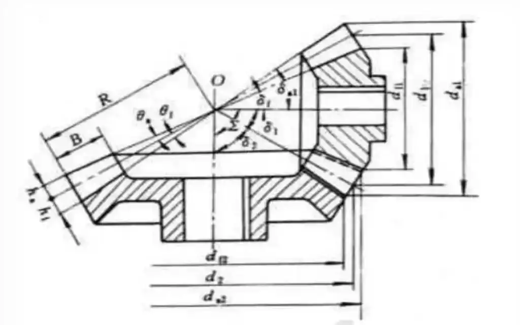
With the crossing angle fixed, the cutter’s tooth profile is calculated using involute geometry corrected for the skiving kinematics. Unlike a conventional shaper cutter (which profiles by pure generation), a power skiving cutter’s effective cutting profile is a function of both the cutter geometry AND the axis crossing angle.
Relief angles on the flanks and tip of each tooth are designed to provide adequate clearance without reducing edge strength below safe limits. For conical cutter designs — which Nobeve recommends for most internal spline applications — the relief geometry is built into the taper, allowing the cutter to be re-sharpened multiple times while maintaining correct profile.
Step 4 — Substrate and Coating Selection
Material selection at this stage determines the cutter’s performance ceiling. Nobeve offers two primary substrate options for power skiving cutters, each with distinct strengths:
| Dimension | W-Series (Solid Carbide) | P-Series (PM-HSS) |
| Substrate | WC+Co (tungsten carbide) | BÖHLER PM-HSS (Austria) |
| Cutting Speed (Vc) | 120–300 m/min | 60–150 m/min |
| Hardness Handled | Up to HRC 50 | Up to HRC 30 |
| Toughness (Anti-chip) | Moderate — needs rigid spindle | Excellent — handles vibration |
| Coating | BALINIT® ALTENSA | BALINIT® ALTENSA |
| Cooling Required | Oil cooling | Oil cooling (mandatory) |
| Best For | Hard materials, small crossing angles on CNC | Tough/soft materials, older machines, no-chip-risk |
| Precision Grade | DIN AA | DIN AA |
For most internal spline applications on well-maintained CNC power skiving machines, Nobeve recommends the W-Series solid carbide cutter when workpiece hardness exceeds HRC35. For softer steels, high-toughness alloys, or environments where spindle rigidity is a concern, the P-Series PM-HSS cutter offers a significantly lower risk of edge chipping.
Conical vs. Cylindrical Cutter Design: Which Is Right for Your Spline?
Both the W-Series and P-Series are available in conical and cylindrical configurations. The choice between them is not aesthetic — it has direct functional implications for your process.
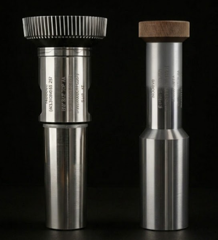
Conical Design: The Default for Internal Splines
Conical power skiving cutters are the standard recommendation for internal spline cutting for several reasons:
- Built-in clearance: The taper automatically provides flank clearance along the tooth height, reducing interference risk in tight bores.
- Re-sharpenability: Each re-grind along the taper maintains correct profile geometry with only a minor diameter reduction — typically 5–8 re-grinds are achievable before the cutter is retired.
- Chip control: The tapered geometry improves chip evacuation in enclosed bore environments where chip packing is a risk.
Cylindrical Design: When Crossing Angles Are Small
Cylindrical cutters are preferred when the available axis crossing angle is very small (under 10°), typically due to a combination of small bore diameter and high tooth count. In this configuration, Nobeve’s W-Series carbide cutters offer a clear advantage: their high rigidity tolerates the reduced cutting efficiency that comes with small crossing angles, maintaining dimensional consistency over long production runs.
The tradeoff is that cylindrical cutters cannot be re-profiled to the same degree as conical designs. Nobeve’s engineering team will advise on which configuration makes sense based on your specific bore, module, and production volume.
Three Common Mistakes That Destroy Custom Skiving Tool Performance
Mistake 1 — Using a Carbide Cutter on an Under-Rigid Machine
The single most frequent cause of premature carbide cutter failure is spindle vibration. The W-Series solid carbide cutter is highly rigid and efficient, but it does not absorb vibration — it transmits it directly to the cutting edge, which leads to chipping. If your machine’s spindle has any runout above 2 μm, or if your fixturing allows any workpiece movement, carbide is the wrong choice. Switch to PM-HSS (P-Series) and address the machine rigidity separately.
Mistake 2 — Ignoring the Protuberance Requirement
Internal splines that require a root undercut (protuberance) to allow for grinding or to achieve a specific fit class cannot be cut with a standard involute profile cutter. The protuberance must be designed into the cutter’s tooth tip geometry. Ordering a cutter without specifying the protuberance requirement — or providing an incomplete drawing — is the second most common cause of scrapped splines.
Nobeve’s free engineering evaluation (see CTA below) specifically checks for this requirement in submitted DXF/DWG/STEP files before any manufacturing begins.
Mistake 3 — Underspecifying the Crossing Angle
Manufacturers sometimes specify only module and tooth count when ordering a custom cutter, assuming the supplier will calculate the crossing angle. But without knowing your specific machine’s spindle geometry, bore depth, and shoulder dimensions, no supplier can correctly determine this — they can only guess. Always provide a full bore drawing, including all clearance dimensions, when requesting a custom power skiving cutter.
What BALINIT® ALTENSA Coating Actually Does for Your Cutter
Both Nobeve’s W-Series and P-Series skiving cutters are coated with BALINIT® ALTENSA from Oerlikon Balzers — one of the most advanced PVD coatings available for gear cutting tools. But what does this coating actually accomplish?
- Hardness: ALTENSA provides a surface hardness of approximately 3400 HV, significantly reducing abrasive wear on the cutting edge flanks.
- Temperature resistance: The coating maintains its properties at temperatures up to 1100°C — critical in power skiving, where the cutting zone reaches high temperatures despite oil cooling.
- Friction reduction: The low coefficient of friction (approximately 0.35 against steel) reduces built-up edge formation and improves surface finish on the workpiece.
- Oxidation resistance: Extends tool life in oil-cooled environments where thermal cycling causes repeated expansion and contraction at the cutting edge.
For PM-HSS substrates like those used in the P-Series, ALTENSA coating compensates for the substrate’s lower inherent wear resistance — effectively bridging the gap between PM-HSS and carbide in terms of tool life on softer materials. This is why Nobeve applies high-end coatings even to HSS-based tools: the coating carries a significant share of the wear burden, extending re-grind intervals and reducing cost per part.
Extending Your Gear Tooling Strategy Beyond Power Skiving
Internal spline cutting with power skiving tools is one part of a broader gear manufacturing toolkit. If your production also involves external gears or spur/helical profiles, Nobeve’s hob range covers the full spectrum:
- K-Series High-Speed Dry Cutting Hobs — for high-volume external gear hobbing at up to 300 m/min, dry or oil-cooled, on materials up to HRC 55 with AT coating.
- G-Series Hard Cutting Hobs — specifically engineered for skiving and finishing hardened gears (HRC45–62), ideal for post-heat-treatment operations.
- N-Series Low-Speed Soft Cutting Hobs — optimized for traditional wet-cut environments and legacy gear hobbers, providing Nobeve precision at an accessible ROI for lower-volume production.
For a complete overview of Nobeve’s product range and technical specifications, visit the Nobeve official website or the About Nobeve page.
Frequently Asked Questions (FAQ)
Q1: What information do I need to provide to get a custom power skiving cutter quote?
At a minimum, you should submit a DXF, DWG, or STEP file of the target spline, including bore diameter, spline module, tooth count, pressure angle, helix angle, root clearance, and any protuberance requirements. If your machine’s spindle specification is available (max RPM, spindle taper, runout spec), including that information will allow Nobeve’s engineers to optimize the crossing angle precisely. The more complete your drawing package, the faster the engineering evaluation and the more accurate the cutter geometry.
Q2: Can Nobeve reverse-engineer a worn or broken skiving cutter?
Yes. Nobeve’s engineering team can reverse-engineer from physical tools using CMM measurement data or 3D scan files (.STL format). You should also supply a sample of the target workpiece or its drawing, since the worn cutter profile may differ from the as-new profile. Lead times for reverse-engineered tools are typically 3–5 days longer than drawing-based orders due to the additional measurement and verification steps.
Q3: How do I know whether to choose the W-Series carbide or P-Series PM-HSS cutter?
The primary decision factors are workpiece hardness and machine rigidity. If your workpiece is ≤HRC30 OR your machine has any spindle vibration or runout concerns, P-Series PM-HSS is the lower-risk choice. If your workpiece is HRC35–50 AND your machine has rigid spindle bearings with minimal runout (≤2 μm), W-Series carbide will deliver higher speed and longer life. Nobeve’s free engineering evaluation will confirm the recommendation based on your specific parameters.
Q4: What is the typical lead time for a custom power skiving cutter?
For drawing-based orders with complete specifications, Nobeve’s typical lead time is 2–4 weeks depending on cutter diameter, coating schedule, and current production load. Rush orders (7–10 business days) are available for certain specifications — contact Nobeve’s engineering team to check availability for your specific requirement.
Q5: Can the same cutter be used on both a dedicated power skiving machine and a turn-mill center?
Yes. Both the W-Series and P-Series cutters are engineered for compatibility with dedicated power skiving machines and turn-mill composite centers, provided the machine’s C-axis and B-axis (or equivalent) can achieve the required crossing angle and the spindle speed range matches the recommended cutting velocity. Always verify spindle compatibility with your machine tool builder before ordering.
Summary: The Right Custom Cutter Changes Everything
Internal spline cutting with power skiving is a precision discipline where standard tooling consistently falls short. The interference angle, bore clearance, workpiece hardness, and machine rigidity all interact in ways that no catalog product can fully accommodate. Custom cutter design — starting from your engineering drawings and optimizing every geometric variable for your specific part — is not a premium option. For complex internal splines, it is the only reliable option.
Nobeve’s approach combines deep gear geometry expertise with premium materials (BÖHLER PM-HSS, imported WC+Co carbide) and industry-leading coatings (BALINIT® ALTENSA) to deliver skiving cutters that are engineered for your part, not adapted from a standard. Whether you need a conical PM-HSS cutter for tough soft-material splines or a solid carbide cylindrical cutter for high-speed hard cutting, the process starts the same way: with your drawing.
| ** Free Engineering Evaluation **— No Commitment Required Email your DXF, DWG, or STEP files to Nobeve’s engineering team for a free evaluation of your internal spline geometry. We’ll confirm feasibility, recommend the optimal cutter design (W-Series or P-Series), and provide a detailed quotation — typically within 48 business hours. Submit drawings: nobeve-tool.com/contact-us/ | ** Product pages: W-Series Carbide / P-Series PM-HSS |

