
Power skiving is fast - but only when the parameters are right. A poorly configured skiving operation can produce worse results than conventional gear shaping, with burrs, poor surface finish, and shortened tool life negating the process's inherent speed advantage.
This guide covers the three pillars of power skiving parameter optimization: cutting speed, feed rate, and toolpath strategy. Each section provides specific, actionable guidance for production engineers who need to get skiving right - from first-article setup through volume production optimization.
Nobeve's W-Series solid carbide power skiving cutters and P-Series PM HSS skiving tools are used as reference tools throughout this guide, with parameter ranges based on real production applications.
Cutting Speed (Vc): The Foundation of Skiving Performance
Cutting speed in power skiving is defined as the relative velocity between the skiving cutter's cutting edge and the workpiece at the point of engagement. It is the single most impactful parameter on tool life, surface finish, and cycle time.
Speed Ranges by Tool Material
| Tool Material | Cutting Speed Range | Best Applications | Nobeve Series |
|---|---|---|---|
| Solid carbide | 120-300 m/min | Internal gears, hardened steel (HRC 40+) | W-Series |
| PM HSS | 60-150 m/min | Soft cutting, larger modules, cost-sensitive | P-Series |
| Coated carbide (ALCRONA PRO) | 150-250 m/min | Hardened steel, long tool life priority | W-Series (coated) |
Speed Selection Principles
- Start conservative, optimize upward: Begin at 70% of the recommended range and increase in 10% increments while monitoring surface finish, tool wear, and spindle load. This approach prevents catastrophic tool failure during first-article setup.
- Material hardness is the primary driver: Higher workpiece hardness requires lower cutting speeds. As a rule of thumb, each 5 HRC increase above HRC 40 should prompt a 10-15 m/min reduction in cutting speed.
- Internal vs. external: Internal gears typically allow slightly higher cutting speeds because the cutting geometry is more favorable (shorter chip length, better chip evacuation in many cases).
- Listen to the machine: Sudden increases in spindle load, unusual vibration, or changes in chip color (from straw to blue to grey) indicate that speed adjustments are needed.
Nobeve's W-Series cutters achieve their best performance at 180-240 m/min for typical automotive internal gear applications (module 1.5-3.0 mm, HRC 32-45).
Feed Rate: Balancing Surface Finish and Productivity
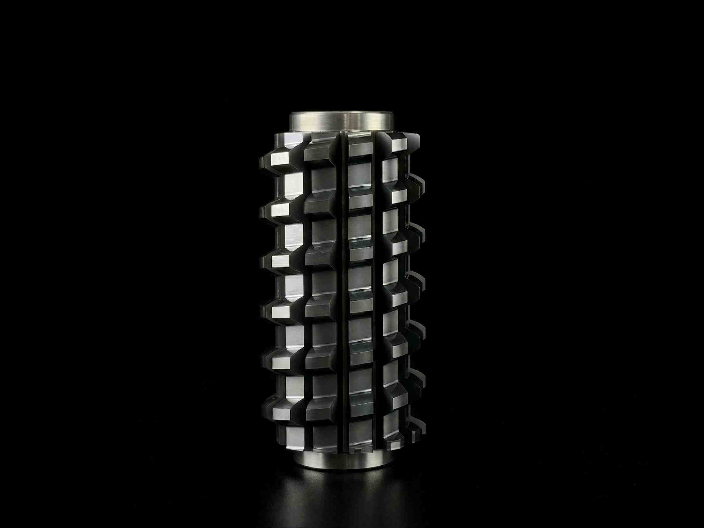
Feed rate in power skiving is typically expressed as feed per tooth (fz) - the distance the cutter advances for each tooth engagement. This parameter directly controls surface finish, chip thickness, and cutting forces.
Feed Per Tooth Guidelines
| Condition | Feed per Tooth (fz) | Expected Surface Finish |
|---|---|---|
| Finishing pass (soft steel) | 0.03-0.05 mm/tooth | Ra 0.8-1.6 um |
| Semi-finishing (pre-hardened) | 0.05-0.08 mm/tooth | Ra 1.6-3.2 um |
| Roughing pass | 0.08-0.15 mm/tooth | Ra 3.2-6.3 um |
| Hardened steel finishing | 0.02-0.04 mm/tooth | Ra 0.6-1.2 um |
Feed Rate Optimization Tips
- Exit burr is feed-sensitive: If you're getting excessive burrs at the tooth exit edge, reducing feed per tooth by 20-25% is often the quickest fix. The thinner chip at exit produces a cleaner edge break.
- Axial vs. tangential feed: In power skiving, the feed direction is typically axial (along the gear's axis). The axial feed rate is the product of feed per tooth, number of cutter teeth, and cutter speed. Ensure your CAM post-processor calculates this correctly.
- Chip thickness matters: Too-thin chips (feed too low) can cause rubbing rather than cutting, accelerating tool wear through heat generation without material removal. Too-thick chips overload individual teeth, causing edge chipping.
For detailed feed rate recommendations for specific gear geometries, contact Nobeve's application engineers - they can provide starting parameters based on your specific workpiece material and gear specifications.
Toolpath Strategy: How the Cutter Moves Through the Gear
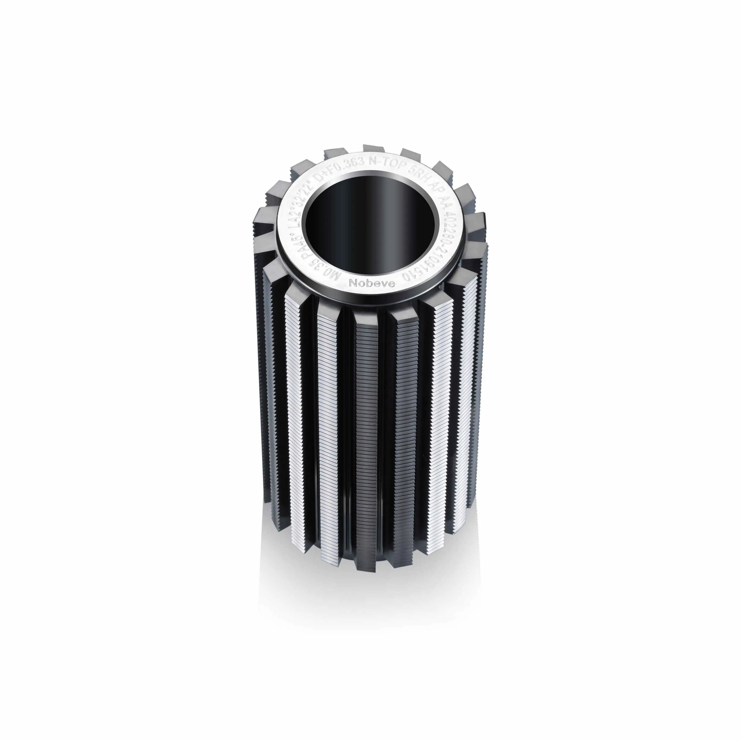
The toolpath strategy in power skiving determines how the cutter enters, traverses, and exits the workpiece. This is where advanced CAM programming separates good skiving results from great ones.
Entry Strategy
- Tangential entry: The cutter approaches the workpiece from the side, engaging gradually. This produces the lowest entry shock and is preferred for brittle tool materials (solid carbide) and hardened workpieces.
- Radial entry: The cutter plunges directly into the workpiece. Faster cycle time but higher impact forces. Suitable for tougher tool materials (PM HSS) and softer workpieces.
Traverse Strategy
During the main skiving pass, the cutter moves axially through the gear while both the cutter and workpiece rotate in synchronized fashion. Key considerations:
- Direction of rotation: Climb cutting (cutter rotation matches feed direction) generally produces better surface finish. Conventional cutting produces thicker chips and may be needed for very hard materials.
- Axial step-down: For deep gears, a single-pass skiving operation may not be possible. In such cases, the cut is split into multiple axial passes, each removing a portion of the tooth depth.
- Cross-section approach: Some advanced CAM systems offer cross-section skiving where the cutter approaches the tooth space from the face width direction rather than axially. This can be advantageous for very wide-face gears.
Exit Strategy
The exit is where many skiving problems manifest. A controlled exit strategy is essential:
- Cutter retract during rotation: The cutter should begin retracting radially while the workpiece continues rotating. This allows the final cutting edges to exit cleanly without dragging through the material.
- Avoid direct pull-out: Simply retracting the cutter axially at the end of the pass creates a burr as the last engaged tooth tears through the material.
- Machine-specific canned cycles: Many modern CNC controls (Siemens, Fanuc, Heidenhain) offer dedicated skiving cycles with optimized exit strategies. These are highly recommended over generic G-code programming.
Synchronization and Machine Setup
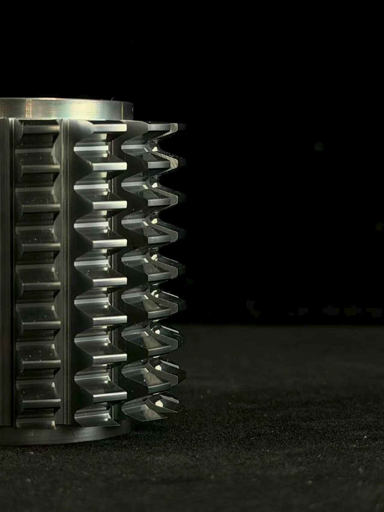
Power skiving requires precise synchronization between the cutter spindle and the workpiece spindle. Any synchronization error results in tooth thickness errors, profile errors, and potential tool damage.
Critical Setup Parameters
- Workpiece spindle speed: Must be precisely calculated from the cutter speed, gear tooth count, and cutter tooth count. Even a small speed error (0.1%) can produce measurable gear errors.
- C-axis accuracy: The workpiece's rotational position must be tracked with encoder resolution sufficient for the required gear accuracy. ISO Grade 6 typically requires C-axis encoder resolution of 0.001 degrees or better.
- Thermal compensation: As the machine warms up during production, thermal expansion can affect synchronization accuracy. Many CNC systems offer thermal compensation tables that automatically adjust for predicted expansion.
First-Article Verification
Before committing to production, verify the setup by measuring:
- Tooth thickness: Must be within specification at the reference circle
- Profile accuracy: Compare measured profile to theoretical involute
- Surface finish: Verify Ra meets requirements
- Burr condition: Check exit edge for acceptable burr height
If any of these measurements are out of specification, adjust parameters systematically - change one variable at a time and re-measure. Changing multiple parameters simultaneously makes it impossible to identify the root cause of any remaining issues.
Frequently Asked Questions
Can I use power skiving on a standard turning center?
Yes - power skiving can be performed on any CNC turning center or mill-turn machine with a live tooling station (C-axis control and synchronized spindle). The key requirements are: adequate spindle power, sufficient rigidity, and C-axis encoder resolution for the required gear accuracy. However, dedicated skiving machines or gear hobbing machines with skiving capability typically offer better rigidity and faster cycle times for high-volume production.
What's the maximum module I can skive?
Practical power skiving is typically limited to modules up to 10-12 mm with solid carbide cutters, though some specialized applications extend to module 15 mm with PM HSS tools. Above these ranges, chip evacuation becomes increasingly challenging, and conventional hobbing or gear shaping may be more practical. For automotive internal gears (typically module 1.5-3.0 mm), power skiving is the ideal process.
How do I reduce cycle time without sacrificing quality?
The three most effective levers for cycle time reduction in power skiving are: (1) Increase cutting speed within the tool's capability, (2) Increase feed per tooth while maintaining acceptable surface finish, (3) Optimize the toolpath to minimize non-cutting time (entry, retract, repositioning). Tools like Nobeve's W-Series solid carbide skiving cutters enable higher speeds than PM HSS alternatives, providing more room for cycle time optimization.
Why is my skived gear noisy in assembly?
Gear noise in skived gears is most commonly caused by: tooth thickness variation (check synchronization accuracy), profile errors (verify hob alignment and cutter condition), or pitch errors (check for spindle synchronization drift). Surface finish also contributes to noise - particularly in high-speed applications. If noise is the primary concern, consider adding a finishing pass with reduced feed per tooth to improve surface finish before the gear goes to assembly.
Conclusion: Optimized Parameters Unlock Skiving's Full Potential
Power skiving's speed advantage is real - but it only materializes when the parameters are right. The three pillars of skiving optimization - cutting speed, feed rate, and toolpath strategy - must work together to deliver the cycle time, surface finish, and tool life that justify the process.
Start with conservative parameters, verify first-article quality, then optimize systematically. This approach minimizes the risk of tool failure and scrap while progressively improving productivity toward the process's full potential.
Nobeve's application engineering team provides parameter recommendations, CNC code templates, and process validation support for W-Series and P-Series skiving tools - helping you get it right the first time.