You’ve finally tracked down a gear hob supplier. You send over the request. And then — silence, a flurry of clarifying emails, or worse, a hob that arrives and doesn’t fit your machine or match your gear drawing. Sound familiar?
For engineers and purchasing teams compiling RFQs for custom gear hobs, the most common point of failure is specification ambiguity. Specifically: the gap between the imperial Diametral Pitch (DP) system used in AGMA-standard drawings and the metric Module (m) system used across ISO/DIN specifications.
Section 1: The Module vs. Diametral Pitch Divide — What Engineers Must Know
If you’ve ordered gears from both American and European suppliers, you’ve already encountered this split. Diametral Pitch and Module are two ways of saying the same thing — tooth size — in different unit systems. But mixing them up in an RFQ means your hob won’t cut the correct tooth form. Full stop.
Diametral Pitch (DP): The Imperial Standard
Typical DP values in industrial applications include: DP 4, 6, 8, 10, 12, 16, 20, 24, 32, and 48. DP is standard in the United States, Canada, and many UK and aerospace applications. If your drawing says “8 DP” or “DP = 12,” you’re working in the imperial system.
Module (m): The Metric Standard
Module is the global default for machinery built in Germany, Japan, China, South Korea, and most of Europe. Automotive drivetrain gears, wind turbine gearboxes, and industrial reducers are almost always specified in Module.
The Conversion Formula — and Why You Should Still Specify Both
This is why Nobeve requests that customers provide the original drawing value — not a converted approximation. Our engineering team confirms the interpretation before any production order is finalized.
Table 1: Module vs. Diametral Pitch — At a Glance
| Dimension | Diametral Pitch (DP) — Imperial | Module (m) — Metric |
| Standard | AGMA (USA, UK) | ISO / DIN (Europe, Asia) |
| Formula | DP = N / d (teeth per inch) | m = d / N (mm per tooth) |
| Common values | DP 4, 6, 8, 10, 12, 16, 20, 32, 48 | m 0.5, 1, 1.5, 2, 3, 4, 5, 6, 8, 10 |
| Relationship | — | m = 25.4 / DP |
| Drawing language | Imperial inch drawings | Metric mm drawings |
| Typical industries | Automotive (US), aerospace, defense | Industrial machinery, wind energy, EVs |
Section 2: The Complete Custom Gear Hob Specification Checklist
Beyond Module or DP, a complete and accurate RFQ requires nine additional parameters. Missing any one of them can result in a delayed quotation, a production error, or — in the worst case — a hob you can’t use. Here’s what to include:
Table 2: Full Specification Checklist for Custom Gear Hob RFQs
| Specification Parameter | What to Provide | Why It Matters |
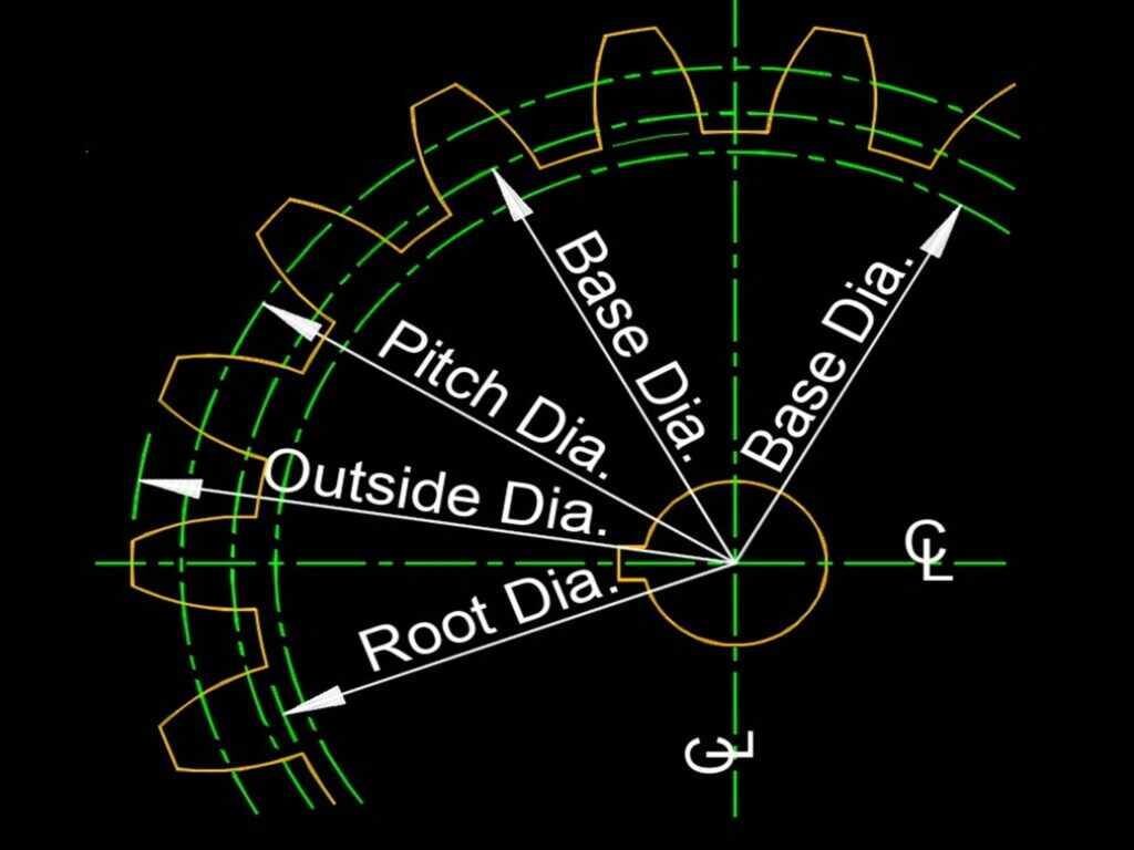
| Module (m) or DP | Exact numeric value (e.g., m3 or DP 8) | Defines tooth pitch — the single most critical parameter |
| Pressure Angle | 14.5°, 20°, or 25° (full-depth or stub) | Determines tooth profile geometry and load capacity |
| Number of Starts | 1, 2, or 3 (single/multi-start) | Affects cutting speed and surface finish quality |
| Hand of Cut | Right-hand (RH) or Left-hand (LH) | Determines hob helix direction for your hobbing machine |
| Outside Diameter (OD) | mm or inches | Ensures the hob fits your machine arbor clearance |
| Bore Diameter | mm or inches, with keyway if needed | Must match your arbor exactly — no guessing allowed |
| Accuracy Class | DIN AA, DIN AAA, or AGMA Class 11–15 | Sets tolerance grades for gear quality |
| Coating | Specify or request Nobeve’s recommendation | Impacts tool life, speed, and dry/wet cutting capability |
| Workpiece Material & Hardness | Material grade + HRC or HB value | Determines substrate (carbide vs. PM-HSS) and coating |
| Number of Flutes (Gashes) | Specify or leave to Nobeve | Affects chip evacuation and tool rigidity |
How to Read Your Gear Drawing for Hob Parameters
If you’re working from a gear drawing rather than a hob drawing, you’ll need to extract the hob parameters from the gear’s specification block. Here’s the typical mapping:
- The gear’s “module” or “diametral pitch” field → becomes the hob’s Module or DP
- The gear’s “pressure angle” field (α) → becomes the hob’s pressure angle
- The gear’s “material” and “hardness” fields → determine substrate and coating selection
- The gear’s “quality grade” (AGMA or DIN class) → sets required hob accuracy
- The gear’s “helix angle” → determines whether you need a helical or straight-flute hob
If you can extract these five data points from your gear drawing, you have everything Nobeve needs to begin an accurate quotation.
Section 3: Pressure Angle — The Parameter Most Buyers Forget
The Three Standard Pressure Angles
- 14.5° (full-depth involute): A legacy standard still found in older industrial gearboxes and replacement parts. If you’re remanufacturing a vintage machine, always verify this is not a 14.5° system before ordering 20°.
- 20° (most common): The overwhelming default for modern industrial, automotive, and commercial gear applications. If your drawing doesn’t specify, it’s almost certainly 20°. But “almost certainly” is not good enough — confirm before ordering.
- 25° (high-load applications): Used in heavy-duty gearboxes where load capacity takes priority over low noise. Common in mining, construction equipment, and high-torque industrial drives.
AGMA standard AGMA 913-A98 and ISO 53 both specify tooth profile standards for involute gearing. If your gear was designed to either standard, include the standard reference in your RFQ — it tells us which tooth form geometry to grind into the hob.
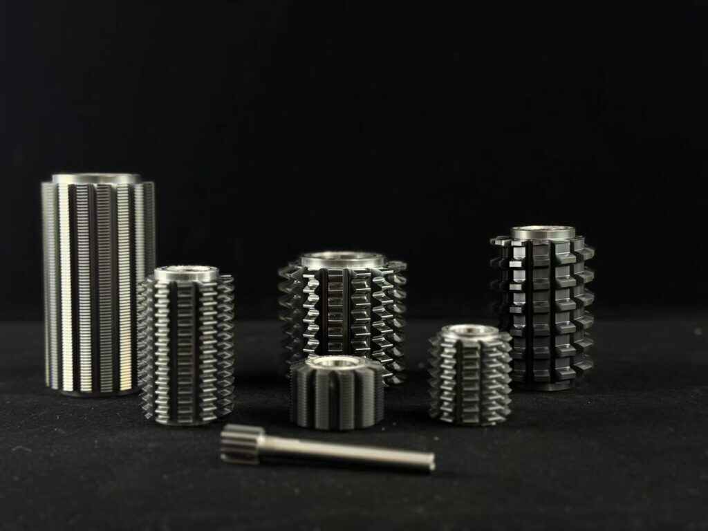
Section 4: Choosing the Right Nobeve Hob Series for Your Application
Once your specification parameters are in order, the next question is substrate and series. Nobeve manufactures hobs across five distinct product lines, each engineered for a specific combination of workpiece hardness, machining speed, and cutting environment.
Table 3: Nobeve Hob Series Selector
| Series | Substrate | Best For | Speed (Vc) | Environment |
| K-Series | Carbide (KF Germany) | High-speed dry/wet, ≤HRC 45–55 | 150–300 m/min | Dry or oil |
| G-Series | Carbide (KF Germany) | Hard-surface hobbing, HRC 45–62 | 120–220 m/min | Oil |
| N-Series | Sintered carbide | Soft gears, legacy machines | 60–150 m/min | Oil |
| W-Series | Carbide (skiving) | Power skiving, ≤HRC 50 | 120–300 m/min | Oil |
| P-Series | PM-HSS (Böhler) | Skiving, soft & tough materials | 60–150 m/min | Oil |
K-Series: Maximum Throughput for Modern Hobbing Machines
G-Series: Hard-Surface Hobbing After Heat Treatment
N-Series: The Reliable Choice for Soft Gears and Legacy Equipment
W-Series and P-Series: Power Skiving Tools for Internal Gears
Section 5: Common RFQ Mistakes — and How to Avoid Them
After processing hundreds of custom gear hob RFQs, Nobeve’s engineering team has identified five mistakes that consistently cause delays or incorrect deliveries. Every one of them is preventable.
Mistake 1: Sending a Converted Module or DP Value
Conversion from DP to Module yields non-standard values (e.g., Module 3.175 for DP 8). Never round to the nearest standard and order without confirming. Always provide the original design value and let the manufacturer confirm which standard hob — or what custom configuration — is correct.
Mistake 2: Omitting Pressure Angle Because You Assumed It’s 20°
20° is the most common pressure angle. It is not universal. Legacy machines, aerospace applications, and certain European gear standards still use 14.5°. A wrong pressure angle produces an unusable hob. Include it every time.
Mistake 3: Not Specifying the Accuracy Class
DIN AA and DIN AAA designations correspond to AGMA Class 11 and Class 12–13 respectively. The accuracy class directly affects grinding time, inspection cost, and price. If you don’t know which class your application requires, specify your target gear quality class and let Nobeve back-calculate the required hob accuracy.
Mistake 4: Leaving Bore Diameter Off the Drawing
A hob that arrives with the wrong bore is useless without an expensive re-boring operation. Always specify bore diameter, bore length, and whether you need a keyway. Include the keyway width and depth if applicable.
Mistake 5: Specifying the Workpiece Material Without the Hardness
“Mild steel” or “alloy steel” is not enough. We need the actual hardness value (HRC or HB) to select the appropriate substrate and BALINIT® coating. An alloy steel at HRC 28 and the same alloy at HRC 55 require completely different hob configurations. Skipping this step leads to tool underperformance or premature failure.
Section 6: How Nobeve Processes Both Metric and Imperial Drawings
Nobeve is headquartered in Jiangsu, China, and serves customers across North America, Europe, and Asia-Pacific. This means our engineering and manufacturing team works fluently in both AGMA (DP-based, inch) and ISO/DIN (Module-based, metric) frameworks — every week.
Here’s how our custom order workflow operates:
- Drawing Review: You submit your gear drawing or hob specification in any format (PDF, DXF, STEP, or written specification). Our team reviews it and confirms the pitch system (DP or Module), pressure angle, and accuracy class.
- Engineering Confirmation: We return a written confirmation of our interpretation before production begins. This step catches unit conversion errors and ambiguous drawing callouts before they become manufacturing problems.
- Substrate and Coating Selection: Based on your workpiece material and hardness, we recommend the optimal substrate (carbide or PM-HSS) and BALINIT® coating (ALCRONA PRO or ALTENSA). You approve or request changes.
- Production and Inspection: The hob is manufactured to your confirmed specification. Every hob is inspected against the specified DIN or AGMA accuracy class before shipment.
- Delivery and Technical Support: You receive your hob with a full inspection report. Our team is available to answer application questions after delivery.
Frequently Asked Questions (FAQs)
Q1: What is the difference between Diametral Pitch (DP) and Module?
Both describe tooth size, but they use different unit systems. Diametral Pitch (DP) is used in the imperial system (AGMA standards, common in the US and UK) and is defined as the number of teeth per inch of pitch diameter. Module is used in the metric system (ISO/DIN) and equals the pitch diameter in millimeters divided by the number of teeth. They are mathematically related: Module = 25.4 / DP. Nobeve can manufacture hobs to either standard.
Q2: Can Nobeve process both inch (imperial) and metric drawings?
Yes. Nobeve’s engineering team is fully fluent in both AGMA (inch-based) and ISO/DIN (metric-based) standards. Simply send your drawing in whichever format your design was created in — we will confirm the interpretation before production begins to prevent any unit-conversion errors.
Q3: What information is absolutely required to quote a custom gear hob?
At minimum: (1) Module or Diametral Pitch, (2) Pressure angle, (3) Number of teeth on the workpiece gear, (4) workpiece material and hardness (HRC/HB), (5) required accuracy class (DIN or AGMA), and (6) bore diameter or shank style. The more detail you provide, the faster and more accurate our quotation will be.
Q4: How does workpiece hardness affect which hob series I should order?
Workpiece hardness is a key selection driver. For soft materials (≤HRC 30), the N-Series or P-Series offer excellent toughness and chip control. For medium-hard materials (≤HRC 45), the K-Series carbide hobs with Alcrona Pro coating are the preferred choice. For hard-surface hobbing (HRC 45–62), the G-Series with ALTENSA coating is specifically engineered for that regime. Nobeve will always confirm the correct series during the RFQ process.
Q5: What is a ‘number of starts’ on a gear hob, and should I specify it?
The number of starts refers to how many helical threads the hob has. A single-start hob offers the highest accuracy; a two- or three-start hob cuts faster but may slightly reduce precision. If your application prioritizes accuracy (DIN AAA), specify single-start. If throughput is critical for softer gears, a multi-start hob may be appropriate. If unsure, Nobeve’s engineers can recommend the optimal number of starts based on your machine speed and gear quality requirements.
Q6: What is the lead time for a custom gear hob from Nobeve?
Lead time depends on module size, complexity, and current production load. Standard custom hobs typically ship in 4–8 weeks. Nobeve provides confirmed lead times with every formal quotation. Rush production is available for select specifications — contact us to discuss your timeline.
Conclusion: Get Your Custom Gear Hob Right the First Time
Nobeve manufactures custom gear hobs across five product series — K, G, N, W, and P — covering every combination of workpiece hardness, machining speed, and cutting environment. Our team processes both AGMA (imperial/DP) and ISO/DIN (metric/Module) drawings without requiring you to convert anything first.
Ready to specify the right gear tool for your next project? Reach out to Nobeve’s engineering team through the contact page, or download series-specific technical data sheets directly from nobeve-tool.com. Your next production run deserves better than ‘good enough.’
External Reference
- AGMA Gear Standards Overview — American Gear Manufacturers Association (AGMA) — authoritative source for AGMA gear standards and gear nomenclature.

