
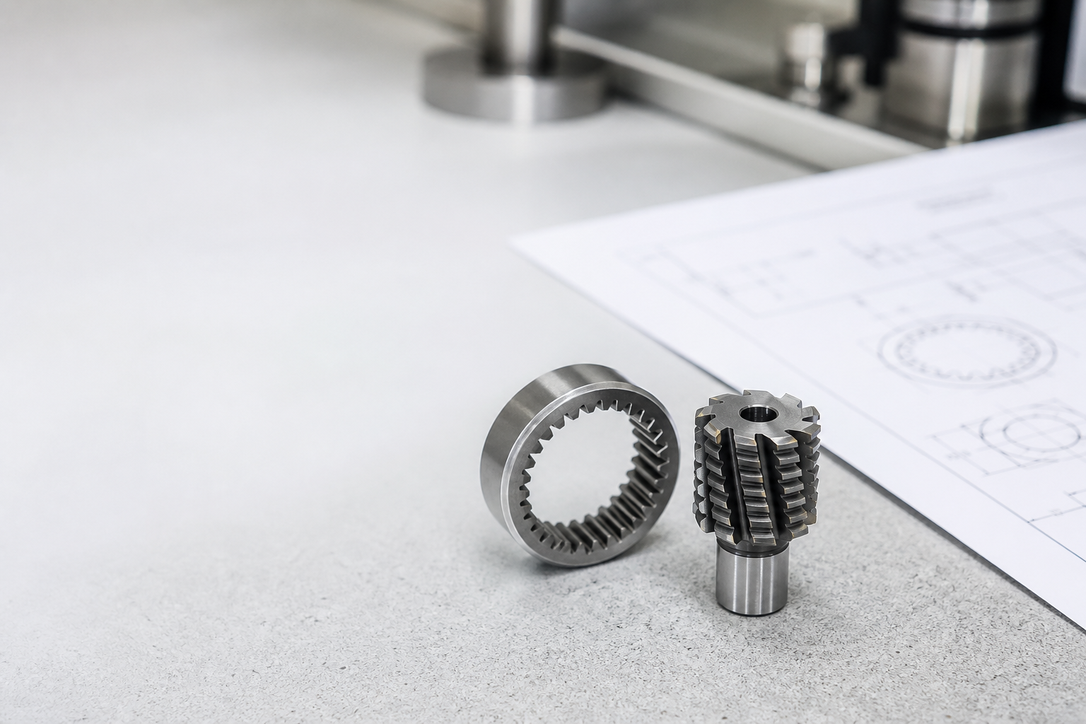
Internal Spline Power Skiving Tool Inquiry: Machine and Part Data to Prepare
An internal spline may look fully defined once module and tooth count are known. For a power-skiving tool inquiry, that is not enough: the cutter must work inside the bore while avoiding interference with the bore wall and nearby shoulders. Send the part and machine information together so the geometry can be reviewed before a tool is specified.
This checklist is for an engineering review, not a substitute for one. It helps manufacturing engineers and purchasing teams describe the actual part, machine condition and production bottleneck in a form that can be evaluated.
Start with the complete spline drawing
Provide a DXF, DWG or STEP file of the target spline. The first-pass drawing package should identify:
- Bore diameter and bore depth.
- Module, tooth count, pressure angle and helix angle.
- Root clearance and any protuberance requirement.
- Shoulder dimensions and other clearance features around the bore.
- Any specified fit class or profile requirement.
These fields give the engineering review the geometry needed to consider cutter-body clearance. If the drawing omits a clearance feature, identify that gap rather than assuming a catalogue tool will fit.
Explain the crossing-angle and clearance constraints
For internal spline power skiving, the cutter operates inside the bore. The angle between the cutter and workpiece spindles affects both the available clearance and the cutter engagement. The submitted bore geometry, spline parameters, shoulder clearances and machine spindle arrangement therefore belong in the same inquiry.
Do not ask a supplier to select a crossing angle from module and tooth count alone. Give the bore depth, shoulder dimensions, cutter-side mounting constraints and the machine’s available axis arrangement. The engineering team can then assess feasible geometry for the specific part.
Record the workpiece condition at the cut
State the workpiece material, material condition and measured hardness with its scale. Also state whether the operation is before or after heat treatment. This gives the review a defined material condition instead of a broad description such as “alloy steel.”
If a cutter substrate or coating is requested, treat it as a question for the review rather than a pre-approved selection. Material condition, machine rigidity and the requested process must be checked together.
Include the machine condition and bottleneck
Add the machine type, maximum spindle speed, spindle taper, available axis arrangement, known runout condition, cutter mounting and workholding arrangement. If available, include oil-cooling details and the intended process route.
Describe the current production bottleneck plainly: for example, an interference concern, observed vibration, edge chipping, chip packing, profile deviation or an unproven setup. State where it occurs and attach relevant inspection or process records. This distinguishes a reviewable condition from an assumed root cause.
Keep the request scope clear
An internal-spline power-skiving inquiry is a cutter-and-process package review. It is not the same as a gear-hob request. If you are sourcing an HSS hob for a separate hobbing operation, identify it as an HSS hob sourcing request. If you need a carbide hob, identify the hobbing machine and application separately. Do not combine either request with a carbide power-skiving package without its own machine condition, cooling and part-data review.
For a related explanation of internal-spline cutter design, see Custom Power Skiving Cutters for Internal Splines. For the wider product context, see Power Skiving Tools.
Send a concise review package
Before requesting a quotation or recommendation, send the spline drawing, clearance dimensions, workpiece condition, machine and spindle details, cutter mounting, cooling information, current parameters if known, and the actual bottleneck to the Nobeve engineering team. The review can then focus on whether the geometry and machine context support the requested internal-spline power-skiving tool.
FAQ
Which spline details are essential for the first inquiry?
At minimum, provide the target spline drawing with bore diameter, module, tooth count, pressure angle, helix angle, root clearance and any protuberance requirement. Include bore-depth and shoulder-clearance dimensions so the cutter-body clearance can be evaluated.
Why include machine data with the drawing?
The feasible crossing-angle arrangement depends on the part geometry and the machine setup. Include the machine’s spindle and axis information, mounting arrangement and available speed range so the application can be reviewed for that equipment rather than in the abstract.